Metal Mesh Foil
Bearings for Oil-Free Turbomachinery
MAJOR APPLICATION: Cost effective gas foil bearing technology for high speed
oil-free turbomachinery
Sponsor: Turbomachinery Research Consortium
(07-11) , hardware donated by Honeywell Turbocharging Systems
Objective: To evaluate performance of metal-mesh foil
bearings for automotive turbochargers.
Significance:
High temperature, high speed oil-free
rotating machinery needs of a proven low friction bearing technology to give
adequate load support (stiffness) and with enough damping to limit rotor
synchronous responses and avoidance of rotordynamic instability. Gas foil bearings are a reliable and proven
technology, albeit too costly. The
present research aims to replace the foil structures with a cost effective,
metal mesh structure for use in automotive turbochargers. Prior experiments
conducted at Turbomachinery Laboratory demonstrate metal meshes have a superior
damping performance at high temperatures and in an oil free environment in
comparison with squeeze film dampers.
More details from Turbo Expo Paper
GT2009-59315, “Measurements of Structural Stiffness and Damping
Coefficients in a Metal Mesh Foil Bearing”
Test MMFB & Experimental FacilitY
Figure 1 shows a schematic representation
of a metal mesh foil bearing.
Figure 1 Schematic representation of
a Metal mesh-foil bearing
Figure 2 shows
the photograph of a prototype bearing. The MMFBs employ commercially available
ring shaped metal mesh as the elastic support under a thin top foil. The
prototype bearing uses a metal mesh ring made of copper wires, owing to the large
structural damping offered by copper meshes . The top foil, a smooth arcuate
surface 127µm thick, is in contact with the journal when not in operation. Note
that, at high rotor speed operation, a thin hydrodynamic air film separates the
top foil and the rotating journal. Hence, any wear of the journal or the
bearing is absent while the rotor is airborne.
Figure 2 Metal mesh-foil bearing
prototype
Honeywell Turbo
Technologies donated two ball bearing turbochargers (TC), series T25, for this
TRC funded project. The TC unit does not have a compressor but a stub shaft, 5
mm in diameter and 35 mm in length, to hold a miniature test journal. The compressor impeller and volute of the
original TC are removed to expose the overhanging shaft. A journal of diameter
28 mm and length 55 mm is press fitted on the TC shaft end and fastened with a
nut.
Figure 3 shows a
schematic front view of the test bearing, journal, and the devices for
measurement of torque, applied load and temperature.
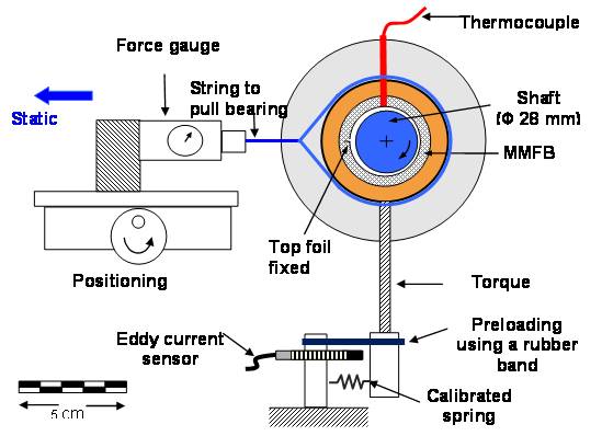
Figure 3 Metal mesh-foil bearing
test setup for measuring drag torque
More details from AHS conference paper, “Measurements
of Drag Torque, Lift-Off Speed and Temperature in a Metal Mesh Foil Bearing”
Figure 4 shows a schematic view of the test rig for identifying the bearing rotordynamic force coefficients.
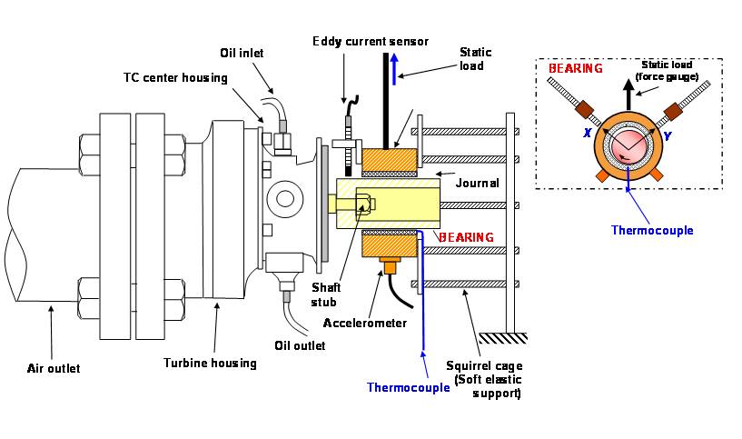
Figure 4 Schematic view of MMFB mounted on shaft of turbocharger drive system. Inset
shows two stingers for application of dynamic loads along two orthogonal
directions
2008-10 work:
Figure 5 shows the journal speed and
bearing drag torque versus time during a lift-off test cycle with an applied static
(pull) load of 17.8 N (4 lb). The rotor accelerates beyond the bearing
lift of speed (~ 28 krpm) to a steady speed of 65 kprm, and then decelerated to
rest. As the rotor starts to spin, rubbing between the journal and top foil
surfaces generate a sharp peak in bearing torque (~ 110 N-mm). Once the journal
starts rotating, the torque falls rapidly. Further, the bearing operates in a
mixed lubrication regime with partial asperity contacts, until the thin air
film completely separates the two surfaces. The airborne journal, at a steady
speed of 65 kprm, offers a significantly smaller drag torque of ~ 3.2 N-mm,
i.e. 3% of the peak (break-up) torque. While decelerating to rest, the journal
comes into physical contact with the top foil and causes a sharp peak in the
drag torque (80 N-mm).
Figure 5 Rotor speed and bearing torque versus time during a lift-off
test cycle for applied static load of 17.8 N (4 lb). Manual speed-up to 65
krpm, operation at a constant rotor speed of 65 krpm, and deceleration to rest
Figure 6 shows the
bearing drag torque versus rotor speed, during rotor speedup, for increasing
static loads of 9.6 N, 18.2 N, 26.9 N and 35.8 N. Note that the uncertainty in
drag torque is ± 0.35N-mm for drag torque < 10 N-mm. For each static load, as
the rotor speed increases, initially the bearing drag torque decreases quickly
and, when the journal is airborne, increases gradually with rotor speed.

Figure 6 Bearing drag torque versus rotor speed for increasing static
loads. Measurement during rotor speed-up tests
Figure 7 show that the friction coefficient
f changes only slightly
with rotor speed after the rotor is airborne, i.e. once the MMFB operates with
a hydrodynamic film. The identified f is the lowest for the largest
applied load of 35.8 N. Owing to the very low friction coefficient, f ~0.01 to 0.02 (when the bearing is
airborne), the drag power losses in the bearing are rather small. For example,
at 60 krpm and the highest static load, the estimated power loss, P=Torque x Ω ~ 4 N-mm x
60000 (π/30) = 25.1 W.
Fig. 7 Bearing drag torque versus rotor speed for increasing static
loads. Measurement during rotor speed-up tests
More details from Turbo Expo 2010 conference paper, “ Identification of
Rotordynamic Force Coefficients of a Metal Mesh Foil Bearing Using Impact Load
Excitations”
2010 work:
Estimation of Rotordynamic Stiffness, Equivalent Viscous Damping and Loss
Factor
Figure 8 Photograph of gas bearing
test rig for dynamic load excitations
Figure 9 Close-up view of metal mesh
foil bearing and connections to shakers for dynamic load excitation
2011-12 work: Analytical Modeling and prediction of MMFB Rotordynamic Performance
Updated : Jan 21, 2011