Computational Fluid Dynamics (CFD) Analysis for Wet Gas and
Bubbly Liquid Seals
* Wet gas: has up to 5% liquid volume fraction.
On how millions of nodes and equations
can be useful to learn more about the operation of mechanical elements. CFD
supported by extensive test data.
Who said more is not better?
The work: more number crunching to crunch more learning!
Publications
1.
Yang,
J., and San Andrés, L., 2022, “Making Better Swirl Brakes Using Computational
Fluid Dynamics: Performance Enhancement From Geometry
Variation,” ASME J. Eng. Gas Turbines Power, Vol. 144(2): 021027, https://doi.org/10.1115/1.4051962 (ASME GT2021-58956).
2.
San
Andrés, L., and Yang, J., 2021,”An Analytical Two-Phase Flow Model for
Prediction of Leakage in Wet Gas Labyrinth Seals and Pocket Damper Seals. Is
Simplicity Still Desired?” ASME J. Eng. Gas Turbines Power, Vol. 143(12): 121016, https://doi.org/10.1115/1.4051916
(ASME GT2021-58958).
3.
Yang, J, San
Andrés, L., and, Lu, X., 2019, “Leakage and Dynamic Force Coefficients
of a Pocket Damper Seal Operating Under a Wet Gas condition: Tests vs.
Predictions,” ASME J. Eng. Gas Turbines Power, Vol. 141(11):111001, DOI:
10.1115/1.4044307 (ASME
GT2019-90331)..
4.
Yang, J., and San Andrés, L., 2019, “On
the Influence of the Entrance Section on the Rotordynamic Performance of a Pump
Seal with Uniform Clearance: a Sharp Edge VS. a Round
Inlet,” ASME J. Eng. Gas Turbines Power, 141(3),
pp. 031029. DOI: 10.1115/1.4040742 (ASME GT20018-75414)
5.
San Andrés, L., Yang, J., and Lu, X.,
2019, “On the Leakage, Torque and Dynamic Force Coefficients of an Air in Oil
(Wet) Annular Seal: a CFD Analysis Anchored to Test Data,” ASME J. Eng. Gas
Turbines Power, 141(2), pp. 021008. DOI:
10.1115/1.4040766 (ASME GT20018-77140)
6.
Yang, J., and
San Andrés, L., 2019, “On the Influence of the Entrance Section on the
Rotordynamic Performance of a Pump Seal with Uniform Clearance: a Sharp Edge
vs. a Round Inlet,” ASME J. Eng. Gas Turbines Power, Vol. 141(3), 032109, DOI: 10.1115/1.4040742
(ASME GT20018-75414)
7.
San Andrés,
L., Yang, J., and Xu, L., 2019, “On the Leakage, Torque and Dynamic Force
Coefficients of an Air in Oil (Wet) Annular Seal: a CFD Analysis Anchored to
Test Data,” ASME J. Eng. Gas Turbines Power, Vol. 141(2), 021008, DOI:
10.1115/1.4040766 (ASME GT20018-77140).
8.
San
Andrés, L., and Yang, J., 2018, “The Influence of Corner Shape on the Static and
Dynamic Performance on an Annular Pressure Seal,” Proc. Global Power and
Propulsion Society Forum 18, Zurich, Switzerland, 10-12 January 2018, Paper
GPPS-2018-55 (www.gpps.global )
Sponsors
1. Texas A&M University (TAMU) Turbomachinery Laboratory
(2016-2018).
2. TAMU Turbomachinery Research Consortium (TRC) (2017-2021).
Computational Resources TAMU High-Performance Computing Center &
TAMU Turbomachinery Laboratory Clusters
Research Background
è Cost efficient
subsea factories must rely on multiple-phase flow compression and pump systems
that reduce tieback systems and perform full flow separation on the sea floor.
è Operation
requirements of subsea turbomachinery: ~ 5% liquid volume fraction (LVF) in wet
compressors and up to ~ 90% gas volume fraction (GVF) in pumps.
è It is already
known that seals operating under a wet gas or bubbly flow conditions do affect
system rotordynamic stability.
Objective Sound Engineering to Quantify
the Leakage and Dynamic Forced Performance of Annular Seals under Wet Gas
Conditions!
Project I
Wet Gas
in a Smooth Annular Seal
To complement experimental work by revealing flow field
structures in multiple-phase flow seals through Computational Fluid Dynamics
(CFD) and to validate/update engineering (BFM) predictive tools.
Operating conditions
Supply
pressure: 1.0 ~ 3.5 bar(a); Rotor speed: 3500 rpm
(surface speed 23 m/s);
Inlet
gas volume fraction (GVF): 0, 0.2, 0.4, 0.6, 0.8, 0.9, 1.
Oil
density: 830 kg/m3 & viscosity: 8.2 cP
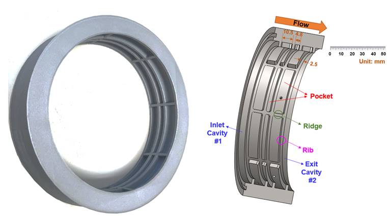
A Wet Smooth Surface Annular Seal
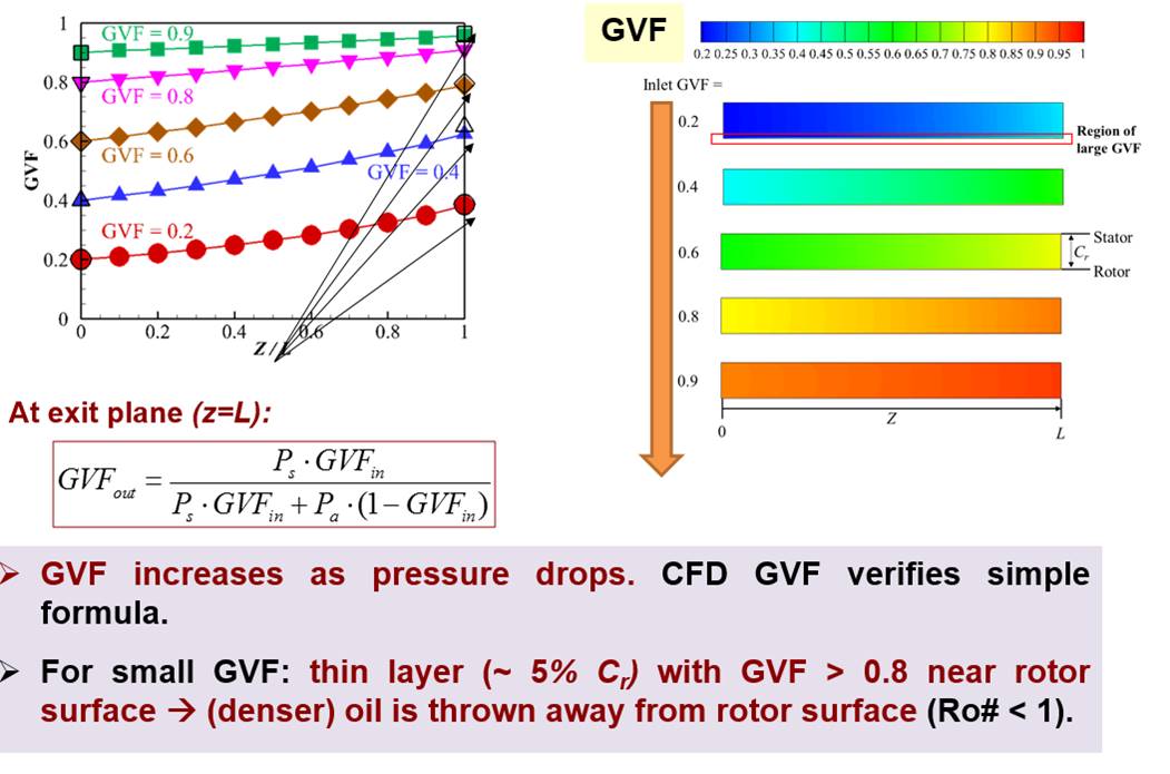
2D CFD Predicted Gas Volume Fraction (GVF) vs axial length
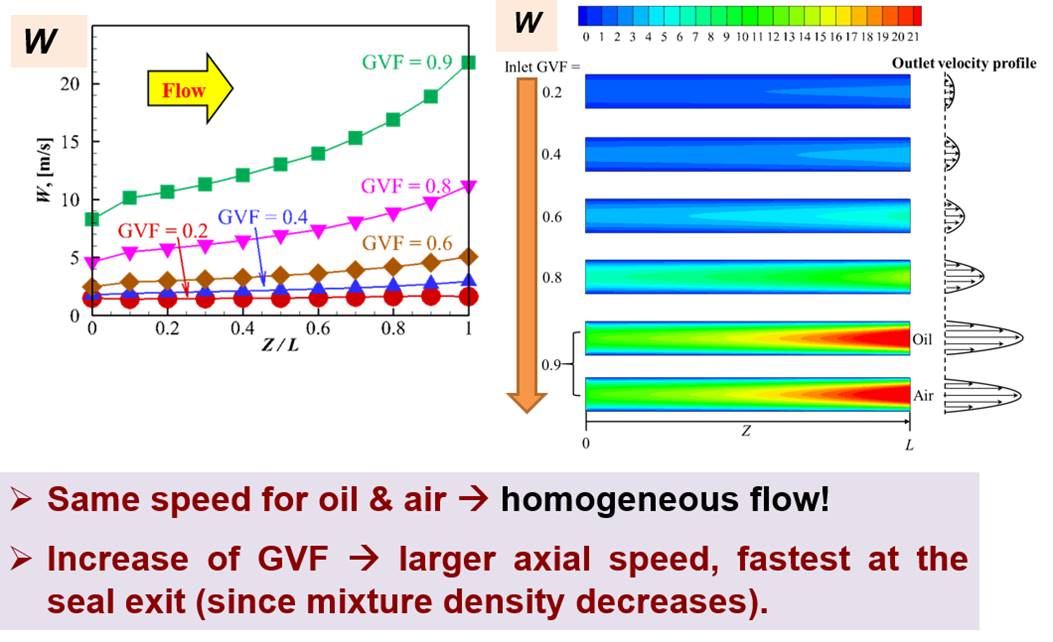
2D CFD Predicted Axial Velocity (W) vs axial length
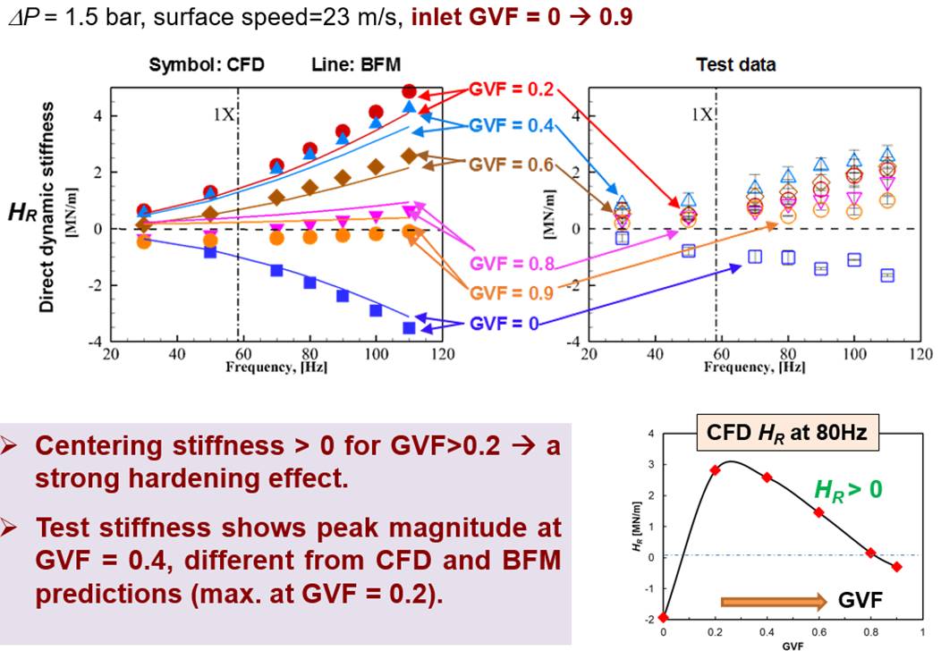
CFD Predicted Seal Direct Dynamic Stiffness against Test Data
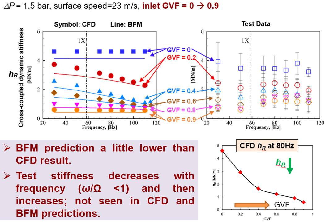
CFD Predicted Seal Cross-coupled Dynamic Stiffness against Test
Data
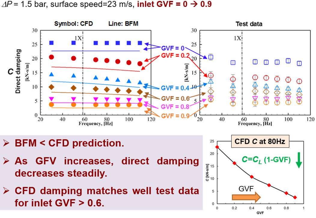
CFD Predicted Seal Direct damping against Test Data
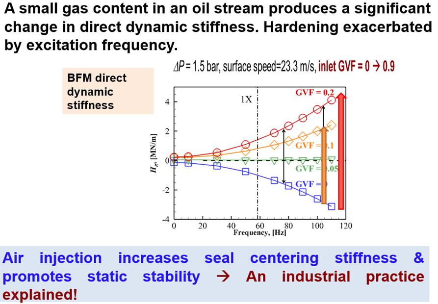
Stiffness Hardening Effect
Conclusions
1. CFD predictions (leakage, power loss) agree with
test data, and also produce high fidelity flow field variables, including
pressure, speeds, and GVF.
2. Operation with a low GVF (< 0.4)
produces a significant hardening effect which makes positive the direct
stiffness. Test data shows same rapid stiffness increase as GVFà 0.2.
3. Stiffness hardening effect is due to
the dramatic reduction in sound speed brought by a small amount of gas (fluid
becomes more compressible).
4. The combination of test results and CFD
and BFM analyses furthers the engineering of seals for wet gas
compressors and bubbly liquids in multiple phase pumps.
Project II
Wet Gas
in a Pocket Damper Seal
Aim of the work
1. Experimentally and
numerically investigate the leakage and dynamic force coefficients of a fully
partitioned pocket damper seal, operating with just air (dry condition) and oil in air (wet
condition).
2. Apply CFD to showcase the flow fields in
pocket damper seal under a wet gas
condition.
Operating conditions
Supply
pressure: 1.0 ~ 3.2 bar(a); Rotor speed: 5250 rpm
(surface speed 35 m/s);
Inlet
liquid volume fraction (LVF): 0, 0.4%. Oil
density: 830 kg/m3 & viscosity 8.2 cP
A Four-Rib, Eight-Pocket Damper Seal
3D Mesh for the Pocket Damper Seal
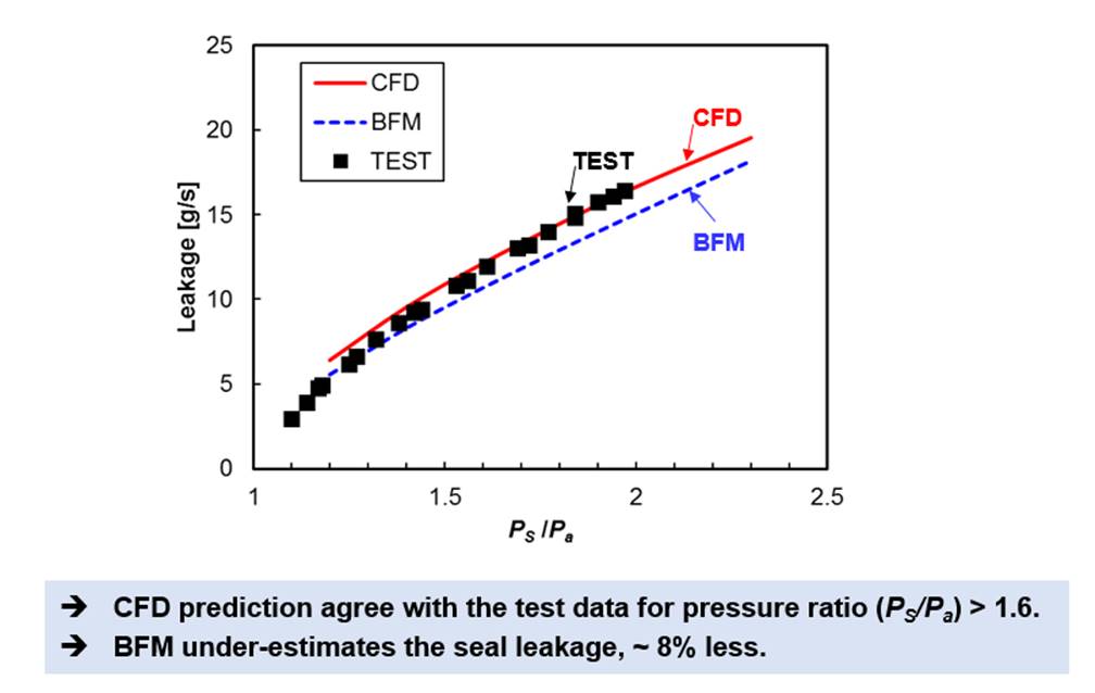
Test Measured, CFD Predicted and BFM Predicted Leakage for the
Pocket Damper Seal Operating with Air
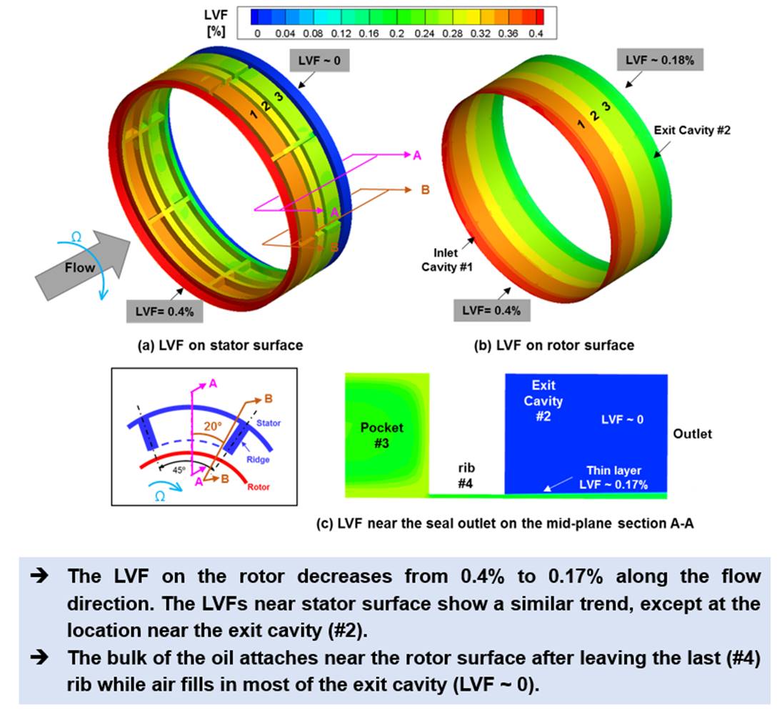
CFD Predicted Liquid Volume Fraction (LVF) Contours on Rotor and
Stator Surfaces (Wet Gas Pocket Damper Seal, inlet LVF = 0.4%)
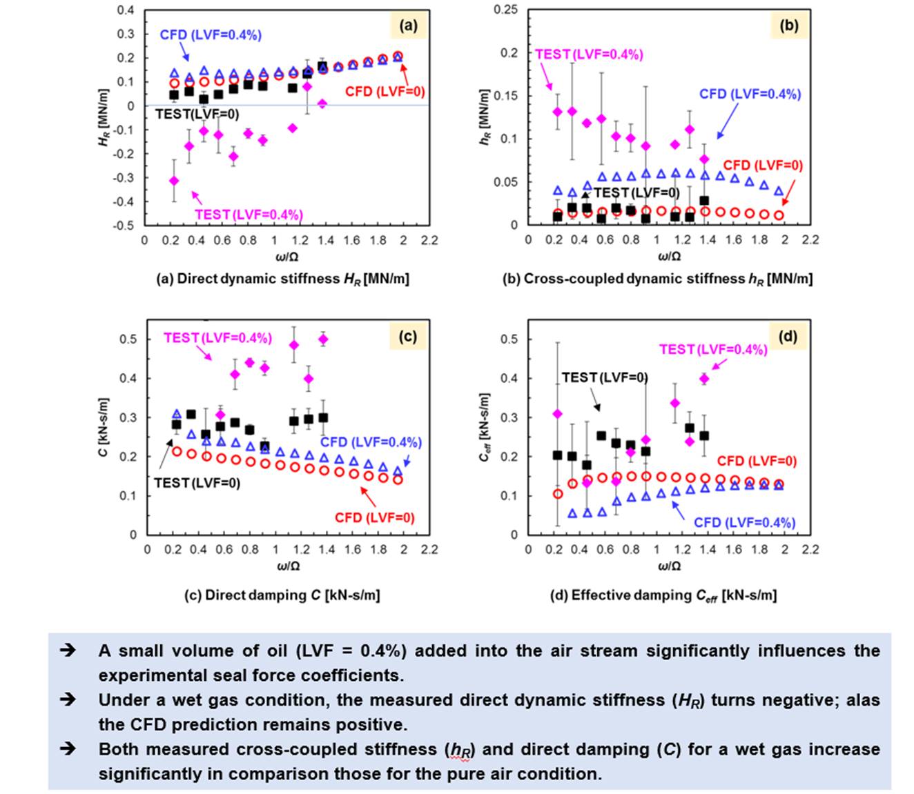
CFD Predicted Dynamic Force Coefficients against Test Data for
Gas Pocket Damper Seal and Wet Gas Pocket Damper Seal (inlet LVF = 0.4%)
Conclusions
1. For dry gas condition, the
measured mass flow rate nonlinearly increases with the inlet pressure. For
operation with a wet gas, the measured leakage increases rapidly as the
liquid density is much larger than that of the gas. CFD predictions match the
recorded leakage.
2. Under a dry gas condition, the experimental direct dynamic stiffness
(HR) increases with excitation frequency, whereas the
cross-coupled dynamic stiffness (hR)
is a minute fraction of HR and showing a high variability as
frequency increases. The test effective damping (Ceff)
is relatively constant as the excitation frequency (w) increases.
3. For a wet gas condition are with
inlet LVF=0.4%, the test derived force coefficients show a large variation
along the two orthogonal directions of forced excitation. The large liquid mass
fraction (57%) makes the dynamic direct stiffness HR negative
though decreasing in magnitude as the excitation frequency increases.
4.
The CFD model for wet gas operation delivers high fidelity
fields, such as pressure, liquid fraction and velocities, which demonstrate the
ridges in a pocket limit the development of the circumferential flow speed
while reducing the liquid content in the middle of a pocket.
Last update: August 11, 2022