Dynamic
Forced Performance of Fluid Film Bearings Operating with Air Entrainment
Sponsor: National Science
Foundation and TAMU Turbomachinery Research 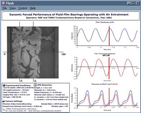 Consortium, June 1998- May 2002
This document presents a
guide to the digital movies obtained in a squeeze film damper operating with
air entrainment. The flow field in a movie correlates with measurements of the
film thickness and pressure for the indicated journal whirl frequency and flow
rate (feed pressure).
A frame of the fluid
motion is shown on the window, with the pressure transducer locations (Z). The
test conditions, lubricant properties, geometry of the SFD, and the camera
settings are listed underneath the movie frame. The three graphs on the right correspond
to the fluid film thickness (h), fluid film thickness velocity (–dh/dt), and the absolute film pressure(s) at the locations of
measurement. The profiles shown in the graphs are aligned with the frames of
the movie. The (moving) red bar shows identical instances of time for the flow
field displayed.
NOTE: Your browser may not allow
downloading *.exe files (flashplayer)
Download here a zipped file containing all videos (4.4 MB) ALL VIDEOS
Digital
movies available for the following test conditions:
(size ~ 0.5-0.8 MB)
|
Movie Filename |
Whirl Frequency (Hz) (Rotor rpm) |
Oil Flow Rate lt/min |
Feed Pressure kPa (psi) |
|
8.33 (500) |
0.1 |
55.1 (8) |
|
|
16.66 (1000) |
0.1 |
55.1 (8) |
|
|
25 (1500) |
0.1 |
55.1 (8) |
|
|
8.33 (500) |
0.3 |
110.2 (16) |
|
|
16.66 (1000) |
0.3 |
110.2 (16) |
|
|
25 (1500) |
0.3 |
110.2 (16) |
|
|
8.33 (500) |
0.5 |
151.5 (22) |
|
|
16.66 (1000) |
0.5 |
151.5 (22) |
|
|
25 (1500) |
0.5 |
158.4 (23) |
|
|
16.66 (1000) |
0.7 |
189.5 (27.5) |
|
|
25 (1500) |
0.7 |
200.0 (29.0) |
In general, higher journal whirl
frequencies and lower feed pressures (lubricant flow rates) are indicative of
the severity of air entrainment.
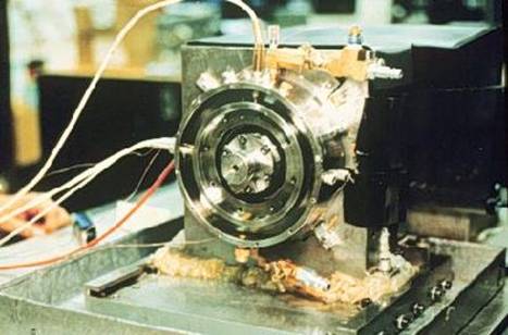
Photograph
of Test Rig
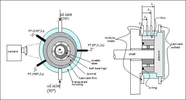
Diagram
of Test Rig and Location of Sensors
L= 31.1 mm (1.22 in),
D=129.3 mm (5.10 in), C=0.254 mm (0.010 in), Z1= 5.6 mm (0.22 in), Z2= 16.7 mm
(0.66 in), Z3= 37.1 mm (1.46 in), PP: Displacement sensor, PT: pressure
transducer, TT: Thermocouple, PG: pressure gauge.
Correlation of Flow Field and
Film Thickness
Learn more, order/read our PUBLICATIONS
© 2011 TAMU
Tribology Group/Turbomachinery Laboratory, Luis San Andrés, P.I.