Effects of air entrainment on response of
squeeze film dampers
 Funded by
National Science Foundation (1999-2002) and TAMU Turbomachinery Research
Consortium (1998-2002)
Funded by
National Science Foundation (1999-2002) and TAMU Turbomachinery Research
Consortium (1998-2002)
High
performance turbomachinery demands the largest power to weight ratios at ever increasing
speeds and light-flexible rotors. These requirements accentuate the two most
commonly recurring problems in rotordynamics, namely excessive steady-state
synchronous vibration and sub harmonic rotor instabilities. Squeeze film
dampers (SFDs) are virtually the only means to introduce damping in aircraft
jet engines and commercial compressors. SFDs have been successfully used to
solve these problems, stabilizing otherwise unstable units. As with most
hydrodynamic bearings, the classical Reynolds equation for thin film
lubrication is generally used to model squeeze film dampers. However,
researchers and users have recurrently reported important discrepancies between
theory and practice.
Our
work in the Laboratory focused on understanding the complex phenomena occurring
in SFDs.
A SFD
comprises of a cylindrical housing, a journal and a thin lubricant film. In
SFDs the journal is typically mounted on ball bearings and does not spin, only
whirls with the shaft. As a result, the hydrodynamic (damping) forces generated
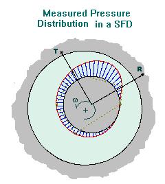
are reactions to the whirling journal velocity. The figure shows a typical
experimental pressure distribution in a SFD as measured in a laboratory test apparatus.
The
pressure profile shown lacks symmetry due to the presence of air in the
lubricant, and which is generally acknowledged to be one of the main sources of
discrepancy between theory and practice. It is generally accepted that, under
high speed operation with high vibration levels, a damper drags air into the
film or releases air that is in solution within the oil. This phenomenon
produces a bubbly mixture of oil and air that replaces the (pure) lubricant,
and is generally misnamed as gaseous cavitation. The resulting complex squeeze
Current
models for the design of SFDs are extensions of the theory developed for
journal bearings. The classical Reynolds equation is solved and boundary
conditions for the definition of a vapor cavitation zone are applied to the
computed pressures. The left figure above shows a measured pressure field that
would agree with such models. In this case, the only effect of the cavitation
by lubricant vaporization is the occurrence of a cavitation zone in which the
pressure is constant and equal to the lubricant vapor pressure at the operating
temperature. The vapor cavitation zone is clearly delimited and repeatable,
thus rendering a predictable cyclic pressure field. Unfortunately, to obtain
this kind of behavior some unusual requirements should be fulfilled. For the
measurements presented, the SFD had to be operated fully submerged in oil and
with a relatively high supply pressure.
Unfortunately,
most SFDs operate with low levels of external pressurization and are open to
the ambient on the sides, thus allowing the formation of a bubbly mixture in
the film as mentioned before. Operation under these conditions results in
completely different pressure profiles, as shown in the figure to the right.
The most noticeable difference is that now the pressure field does not repeat
itself for every cycle of journal motion. Random
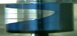
The
figures below show the stationary cavity developed by vapor cavitation in a
steadily loaded journal bearing and the bubbly mixture formed in an orbiting
SFD. Click on the pictures to see more information about them.
 bly
mixture formed
bly
mixture formed
Vapor
cavitation on a journal
bearing Bubbly
Lubricant in a SFD
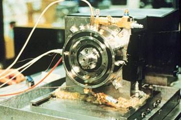
The TRC-SFD test rig is set up for the study of
gaseous cavitation in SFDs. The damper journal is mechanically constrained to perform
circular centered orbits. The dimensions of the open-end damper tested are, Diameter=129
mm, Length=31 mm, Clearance=0.343 mm. The apparatus is
instrumented with four piezoelectric pressure transducers, two strain gage
pressure transducers, two eddy-current displacement sensors, one optical
tachometer, one thermal air mass
The
experimental results correlate the appearance and extent of a zone of constant
pressure, or null pressure generation, with the introduction of air in the
lubricant (void or volume fraction)as shown in the figuresbelow. A 3D representation
of these test results shows a different perspective, and makes evident how the
occurrence of the gaseous cavitation zone results in a reduction of the
squeeze film pressure generation.
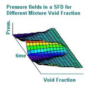
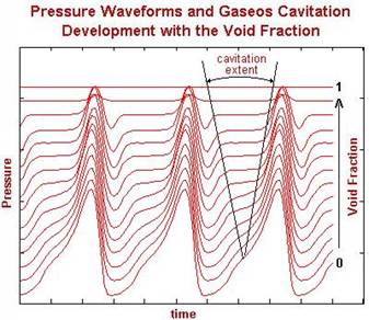
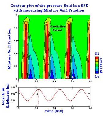
The
measured pressure depicted on the graphs is absolute and makes evident how the
zone of constant pressure takes the value of the pressure at the damper
exit (discharge plane). The contour plot at the right correlates the
squeeze pressure with the local film thickness as a function of time for
different mixture (void fraction) conditions, and shows that the
The
major objectives of the research were to determine experimentally the effect
that air entrainment has on the performance of the SFDs and to develop a model
quantifying these effects so as to enhance our understanding of squeeze film
dampers. The tests and model aid in the design of new dampers and modification
of old ones. Ultimately, the damper hydrodynamic forces exerted on the journal
become the most important factors to be studied, since these forces directly
affect the dynamics of a rotor-bearing system employing SFDs. The experiments
have shown that the presence of air in the lubricant results in reduction of
the damping forces as shown below.
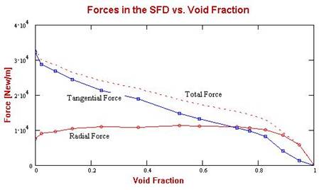
Experimental radial and tangential forces vs air volume content
The
research completed the analysis of the pressures and forces to develop a
semi-empirical theoretical model that accounts for the dynamics of the bubbles
within the lubricant. Modifications to the test rig to perform
è To learn more, order/read our Publications
ACKNOWLEDGMENTS
The support from National Science Foundation (NSF) and the
Turbomachinery Research Consortium (TRC are gratefully acknowledged.